How to generate toposurface in Revit from the Autocad topo file? I received this great question from my blog reader, Nira, and would like to share with everyone this quick way to general topo in Revit.
Here is Nira’s question.
1. I opened a new project, Project Browser > Site View > Insert tab > Link Cad (SUCCESS)
2. I did set true North for the Project following your study.
The site plan was rotating to the wrong command.
e.g. Orientation Project North showed site of plan on True North and Orientation True North showed site of plan on Project North.
Until now I couldn’t find any site that showed how to use Spot Elevation on a AutoCad generated Toposurface.
I even tried with placing points on the generated Toposurface, it does not work.
I changed my tack ticks and drew the Massing Site > Toposurface > Place Point
which generated a perfectly Toposurface. But when I started placing Spot Elevation some of the spots led into a certain point on the center of the Toposurface with ‘0’ as value
Can you help please?
Sure I am happy to help! Here is my response to the questions:
-
For those who haven’t linked any Autocad file before, please check out this blog post “Import AutoCad 2D drawing to your Revit Model“. What Nira mean is to go to Project Browser and click on the Site View, then go to the Insert tab > Link CAD.
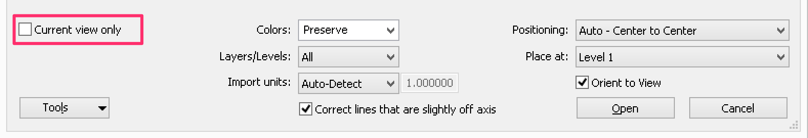
Note: Make sure the Current view only box is unchecked. Checking the box will prevent you from selecting the CAD file to create topo in the step below.
- What goes wrong here? The Site Plan in the AutoCAD file is not oriented based on True North. Here is the proper way to do:
- The Site Plan must be set to orient to True North in the AutoCAD file.
- After the Site plan is linked into Revit, rotate the Site Plan to the Project North position and move it as needed so your building is set correctly on the site. (An analogy is to imagine your building is drawn on a piece of transparent marker board, and your site plan is a piece of tracing paper that is placed on the back of the board. Since the building on the marker board cannot be moved, we will need to move and rotate the tracing paper behind to make the building locate correctly on the site.) Read this post to understand the difference between True North and Project North “Project North vs True North“
- Go to Manage > Project Location Panel > Coordinates > Acquire Coordinates > Select the AutoCAD file. Read this post to understand the difference between Acquire and Publish Coordinates “Setting up True North – Best Practice“
- To test it out, go to Properties > Change the Orientation from Project North to True North to see the site plan orientation change as you switch between these 2 settings.
Generate toposurface in Revit from the AutoCAD file
- First, check these two things in the CAD file:
- Make sure the spot elevation of the contour is set correctly.
- The CAD extends is within 20 miles. If the extend is greater than 20 miles, Revit will give you an error message.
- Ok, the CAD file looks great! Next, go to the Project Browser to open up the Site view, link the CAD file into the Revit project following #1 above.
- To generate the toposurface, go to Massing & Site > Toposurface > Create from Imports > Select Import Instance > Select/Click the CAD file you just linked in.
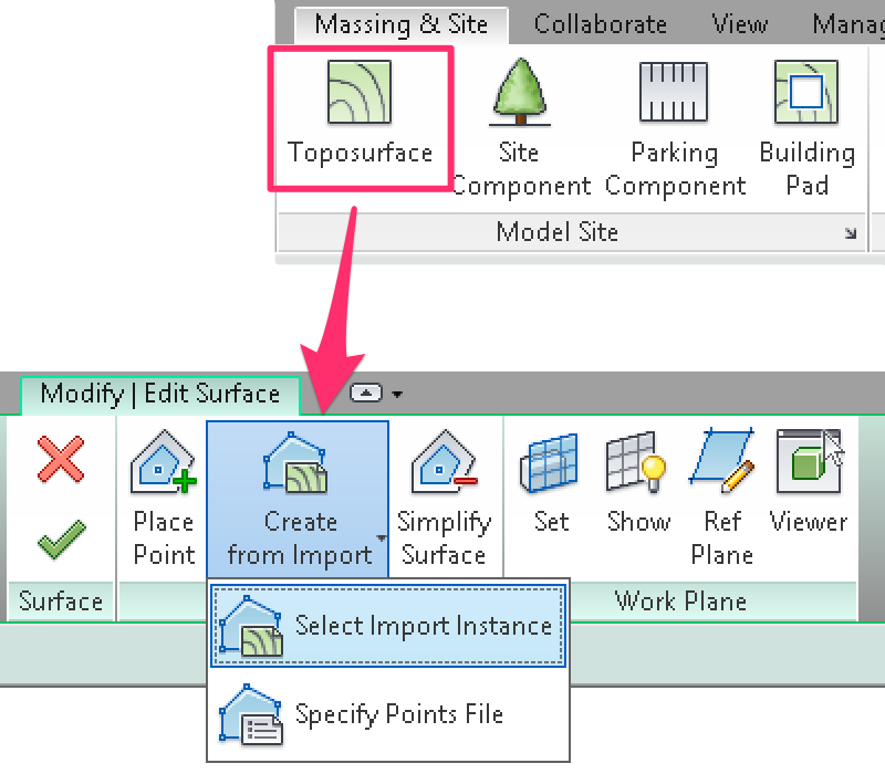
A new window “Add Points from Selected Layers” pops up for you to select the layers you wanted to use to generate the points. Select the layer(s) that correspond to the contour line(s), Revit will collect the point data from the selected layer(s) to generate the toposurface. Now, sit back and see the magic happens… Revit automatically generates the toposurface. Isn’t it sweet?
By taking advantage of this wonderful tool in Revit, this will save you a lot of time and frustration.
Regarding the question about spot elevation reading “0” on the toposurface that was created using Place Point, I would suggest Nira to open up the toposurface in 3D view to see if there is anything odd happening, sometimes seeing the toposurface from a plan view is hard to see the problem when there are so many points on the topo; or consider trying the simple tutorial above to generate a new topo.
Great!! Yes this is a great time-saver tool in Revit, I’ve used it before but I didn’t actually knew unchecking the Current view only box would prevent from selecting the cad file. Thanks.
Very good, thanks.
As another suggestion and related article, do you know of a guaranteed way of using Shared Coordinates effectively between Civil 3D and Revit?