I wrote a post years ago about importing AutoCAD 2D drawing to Revit model, the user interface in Revit has evolved significantly over time and I feel there is a need to revisit this topic.
If you are reading this post, you are properly looking for tutorial on how to bring CAD file into Revit. Here is my question for you:
- Are you trying to import CAD floor plans or details for tracing?
Yes -> Skip question 2 and continue to read this post.
No -> Go to question 2.
- Are you trying to import CAD site plan or Civil drawing to your Revit model?
Yes -> Please read my other post Setting up True North for a Project – Best Practice and download the free PDF tutorial at the end of the post.
No -> Leave me your question in the comment, I will try my best to help you.
Linking CAD file to the model
To bring a CAD floor plan or detail into Revit, open up the View you want to place this CAD file to. That is, bring it to Floor plan View if you want to use the CAD floor plan as a background to build your building model; Drafting View if you want to trace over the CAD detail.
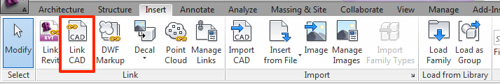
Go to Insert tab > LINK CAD (always LINK*, do no import!)
Link vs. Import
Link* – You can always reload the CAD file to show the latest updates you made by going to Insert tab > Manage Links.
Import – The CAD file is inserted into the model. All changes made to the CAD file will not be updated unless you remove and reinsert the file into the model. Import too many CAD file can overload your model.
It is always a good practice to unload the CAD file once you have finished using it.
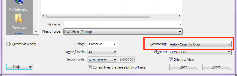
Browse the CAD file you want to bring into your model, under Positioning, select Auto – Origin to Origin. Always make sure the content in the CAD file is close to the (0,0,0) origin. Revit will gives an error message if the content is greater than 20 miles from the origin.
Why Auto – Origin to Origin?
The origin in Revit is called Project Base Point (PBP). When the CAD file is inserted with Auto – Origin to Origin positioning, the CAD origin (0,0,0) will fall on the Project Base Point. The benefit is:
- In cases you are inserting multiple CAD floor plans into the model, this will ensure all the plans lines up properly on each level.
-
The geometry in the CAD file is close to the PBP, Revit don’t like anything that is too far away from the PBP.
Locate the Project Base Point
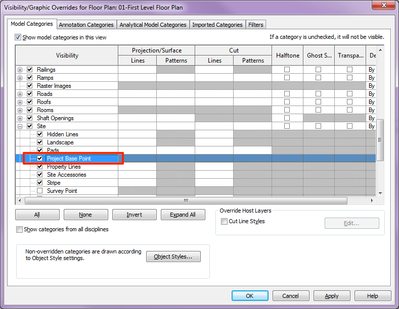
To locate the PBP, open a floor plan view. Go to Visibility/Graphics Overrides (type VG). In the Model Categories > Sites > CHECK “Project Base Point”. A blue icon will now appear in your view. This is the PBP in your model.
Want to learn more?
When you work in a team, it is important to properly set up project orientation to get everyone on the same page. I wrote several posts about this topics:
- Project North vs True North
- Setting up True North for a Project
- Setting up True North for a Project – Best Practice
I was wondering if there was an easy way like in sketch-up where by I can import countours into revit and extrude them? or build up on them?
Thank you
Annabel, sorry for the late reply. There is a way to do import contour to Revit. I always find it convenient to bring in the topo from Civil drawings because all the lines already drawing with Z coordinate assigned. However, it is very likely that the civil topo is drawn miles away from the origin. So make sure you move the topo within 20 miles from origin and clean up all unnecessary lines from the CAD file. I apologize I cannot get into too much detail explanation in here. The concept is to link the CAD topo into Revit with “Auto-Origin to Origin”, go to “Massing and Site” tab, then use the “Toposurface” to generate the topo. Keep in mind to create a separate Revit file for your topo and link that into your building model file. Do not create the topo directly in your building model file. This is to avoid the nightmare if the building ever needs to be moved on the site plan in the future.
Hi,
I read your post and the steps you explained about link a cad file to a model are awesome. Whole post is fully informative and i really appreciate you for this nice post.
Thanks
Hi,
Is there a way to import general notes and text from an Autocad file to a Revit file?
Copy and paste will be the quickest way. In AutoCAD, highlight all the text and copy, Ctrl+C. In Revit, go to Annotation tab > TEXT. With the text box opened, paste the text directly into the text box, Ctr+V. Do some formatting adjustment and you are good to go.
Do you have to have the Revit software to convert AutoCad files or Inventor files to a Revit format?
You will need to run Revit to export Sheets and Views from Revit to AutoCAD. For bringing AutoCAD file into Revit, it is always recommended to ‘link’ the CAD file in and trace on top of it. Once you have finished, remove the CAD file. I know some people ‘import’ the CAD file to Revit and explode it. It is a big NO NO. Do not attempt to do this, it will drive up the size of your Revit file significantly because of all the junk that was bought in once the file is exploded. Hope that answer your question.
hi veng,
How do i send an ecel spreadsheet to autocad and than autocad to import in revite?
please let me know how at louis.chrispin@guest.amec.com
Louis, I have emailed you the response to your questions.
how can i give the slab think in revit.
Abdul, with your floor slab selected, go over to the Properties and select the slab thickness from the pull down list. If there isn’t anything you need, just click the Edit Type and “duplicate” a new floor type. In there you can enter the floor thickness you desire.
hello
can i model a folded architecture in 3d max then import it in revit
cause its hard to be modeled in revit … can i ???
Heba, unfortunately I don’t use 3d max, I don’t have an answer to your question.
How to link autocad file into revit elevation view? It always asks to pock up plane or line or something else, so complicated to achieve but very big need
Hi! I have drawn my multiple floor plans(1st, 2nd and 3rd floor) in one file in Cadd. To link the Cadd file into revit, do I need to separate each floor in different files and then link it? How should I do it? If there are video out there please the link. Thank you 🙂
Donnie, you need to separate the floor plans into 3 separate CADD files, make sure the plans are at the same location when you overlay them and set your plan close to the 0,0,0 origin. Once your cadd plans are ready, start Revit. Open up the First Floor View, follow the instruction in my tutorial Import AutoCAD 2D drawing to your Revit Model to link in your First Floor CADD plan. Next, open up the Second Floor View, and link in the second floor plan. Last, open up the Third Floor View, and link in the third floor plan. The 3 plans should overlay correctly on top of each other. Leave me a note if you have any questions. 🙂
when i am saving a fill to the computer it appears to be slightly off level. I have brought up an older set of drawings which show up fine then insert the new drawings and they seam to level out except for the border still appears off level. What may cause this and how can I fix the problem?
BB King
BB King, I do not quite understand your question. I assumed the “level” you refer to is the level elevation. What do you mean by “the border off level”? I am happy to help if you can further explain your problem. Btw, you can control the level you want to insert the AutoCAD file by correctly assigning the “Place at” Level (see the second image in this blog post, it is located below “Positioning”).
revit 2015
try to copy and paste general notes into revit per your suggestion….must be missing something…no joy
Could you try to be as explicit as possible with each step….controlling text in revit has proven to be a real stumbling block
Andy, are you trying to bring general notes from AutoCAD to Revit or copy general notes between 2 Revit projects? If you are coping text from AutoCAD to Revit, all the formatting will be gone during the copy and paste process. You will have to reformat all the text.
I am trying to use a CAD file for power and data to be visible in my REVIT project without having to model it, but when I place 3-D FF&E families on top, the power and data symbols are buried. Is there a way to show the CAD file “on top” without raising it?
Veng,
Nevermind, we figured it out! 🙂
Hello,
I have to work with imported dwg files and have either turned off or deleted lines
with the ‘query’ tool. I am noticing that these same lines are reappearing when
I reopen the file. I also seem to be losing dimensions that were snapped to the import
symbol whenever the file is reopened.
Am I doing something wrong [aside from having to use imported files]?
Would it make more sense to abandon the imported symbol file and go to
linked dwg?
Thank you – bob
Bob,
Instead of using Import CAD, you should use Link CAD to link in the dwg file. Link CAD gives you the flexible to reload the file if you ever made any changes to the CAD file, while Import CAD is a static file, once the file is imported into Revit, any changes you made in CAD cannot be updated in the Revit model. Another benefit of Link CAD is any dimensions you snapped to the CAD objects will also be automatically updated if you even adjust any object in the CAD file. One more tip: When you are in the Link CAD window, there is a Current View Only check box, click the check box if you want this CAD file to show up in this specific view only, otherwise, the CAD file will show up in all the view associated to the level. (For example, you link the file to Level 1, this CAD file will appear in all Level 1 view you have created.)
Keep in mind anything in Revit “View” is “What you see is what you get”, if you unload the CAD file, the dimensions will disappear as well, but once you reload the file back, the dimensions will reappear again.
If you need to turn off any CAD layer, do it in the VG (Visibility Graphics). In VG, click the Imported Categories tab, you should see your CAD file in there, click the + icon next to the CAD file, uncheck the layer you don’t want to see. Btw, VG changes are view specific, if you need to make the same changes to another view, you either create a View Template to apply to another View or go to VG again in other view and “redo” all the settings.
Thank you Veng for the great response,
I will link cad files as needed in the future. However, I may need to stick with the imported
cad due to time constraints on this particular project.
I would like to clarify your second comment/paragraph: Do the re-appearing dimensions only work
with a linked file and not an imported file? I am not sure why I am losing dimensions [or other revit notation]that have been snapped to imported cad files?
the vg graphics controls for cad files is great info and a nice add to my question!
-again thank you for your help! bob
The imported file is a static file, the dimension should not disappear when you re-open Revit. Sorry, I do not know why your dimensions keep disappearing.
My gf is makeing her exam projekt. She is going to build a nersary home. She got the cad 2d ground project whit hills and etc, from the city where she attentionaly wants it to be build, but when we try and import the it to revit and get the hills to show as 3d it wont eork. It eighter stay flat out ( if she inport it in meter) or it gets realy messed up whit spikes all over. The cad is in meters. But when she inports it whit auto-detect the map that comes up is WAY to small. She hasto zoom in alot to even see it. Can you help?
1. Check the Drawing Units in your CAD file, is the “Length Type” and “Insertion Scale Type” belongs to the same unit type (both are in meters) -> the CAD file was setup truly in meters as you said or actually in millimeters?
2. Instead of using Auto Detect in Revit, specified the “Import Units” when you “link” in the file (depends on your findings in first step, select meters or millimeters). Make sure you are linking in the CAD file, not “import” the CAD file.
Hello Veng,
If I have a building & site of over 500 feet by 400 feet. What scale should I use in Revit? I thought I should use 1/8 but I had to move the elevation markers way out by highlighting and moving with my arrow keys. If 1/8 scale is acceptable, is moving the elevation markers out with my arrow keys the correct way to make my drawing area larger? Thanks.
Jessie
Hey Veng, do you know what I should do in regards to my above question? I just want to make sure I am not messing up the Project Base Point. Thanks!
Moving the Level datum will not change the drawing area. You need to adjust the Crop Region to change the drawing area. For an overall site plan, you can set the scale to 1/16″, it should fit perfectly on a 30×42 sheet. For floor plans, I will set it at 1/8″ scale and break down the plan into multiple areas since the plan will be too large to fit on one sheet.
To move the Level datums, you can either select it and move the blue dot. Take note at the small text next to the Level datums, if the text indicated “3D”, when you stretch the Level line, the stretch will apply to the entire project, meaning you will see the length of the Level line change in other Elevation views as well, but if the text is “2D”, stretching the Level line will only apply to this one view. You can switch between “2D” and “3D” by clicking to this little text. Stretching the Level line will not mess up your Project Base Point, they are two different things.
To show the full extent of the drawing area, you need to adjust the Crop Region. In a plan view, go to “Properties” > Scroll down to “Extents” > Check “Crop Region Vision” . You should now see a box will 1 dot on each side, stretch the box to adjust the drawing area. Another way to adjust the drawing area is to use “Scope Box”. Draw a scope box, go to Properties and apply it to the view. You can apply the scope box to any view.
I wanted to import like 30 to 40 files in a single Revit family, is there a way to do it other than importing them individually ?
Vasanth, are you linking the CADD file to the Revit project file or Revit family? Please clarify. It is very unusual to link the CADD file to a Revit family, we normally link it into the Revit project file. To answer your question, you can only link in one CADD file at a time. The CADD file is always linked into the active View, so when you have have 30 to 40 files, there is no way for Revit to know which view to put those files at.
Subject: Link AutoCad 3D drawing to your Revit Model – Revit 2014
1. I opened a new project. Project Browser> Site > Insert>Link Cad (SUCCESS)
2. I did set true North for the Project following your study.
The site plan was rotating to the wrong command.
e.g. Orientation Project North showed site of plan on True North and
Orientation True North showed site of plan on Project North
Found the site https://www.youtube.com/watch?v=NtJ5VlZMUZ4 which solved my
problem.
Until now I couldn’t find any site that showed how to use Spot Elevation on a AutoCad generated Toposurface.
I even tried with placing points on the generated Toposurface, it does not work.
I changed my tack ticks and drew the Massing Site> Toposurface > Place Point
which generated a perfectly Toposurface. But when I started placing Spot Elevation some of the spots led into a certain point on the center of the Toposurface with ‘0’ as value
Can you help please?
hi veng..i want create a plan from 3D model in revit for my research….but i dont know how to get start..please help me..
hi veng..thanks for your response..actually,i’m really need yourhelp..i dont know how to use revit tool but i have already learn from tutorial..its difficulty to understand..for ur information,i’m final year student..my research is to generate plan from survey data in revit..i have a 3D model from UAV photogrammetry..i’ve imported that
3D model into revit..then i didnt know how to get started with that 3D model..i’m really need your help..please help me veng..
I can explain how to start the model. Can you send me the file? I will see what I can do for you.
Btw, I do not have experience in bringing point cloud data to Revit. But your question draw my interest in doing some research in this area. I found this nice article from Better Revit about generating Revit topo from point cloud data, this will help you to generate the topo in Revit, but for the building, yes, you will need to build it from scratch, and I can help you on that.
http://betterrevit.com/revit/generate-revit-topography-from-point-cloud-data/
Hi
i wants to import CAD file to Rivet but the building is 3-stories and i am not getting how to manage their levels. Kindly mail me the step wise method .
And my second question is about the energy simulation on Rivet . When i run the analysis then it gave an error that convert to masses .
My email id : hamayun2222@gmail.com
Thanks.
Does anyone know how to convert a 2D (AutoCad 2009) file into a 2D Revit 2016 version?
Does anyone know how to convert a 2D (AutoCad 2009) file into a 2D Revit 2016 version? My email id: dhyde2005@yahoo.com
Thanks
Dennis,
You cannot convert AutoCad to Revit. The only way to bring the AutoCad file to Revit is using the Linking tool. Speaking in AutoCAD language, linking in Revit is similar to Xref in AutoCad, any updates you made in the AutoCAD file will appear in the Revit file. Are you trying to convert AutoCAD details to Revit? If that is the case, the proper way to do is to link in the AutoCAD file and trace over it in Revit. There is a “Pick Lines” tool (a green line with an arrow symbol) in Revit, use this tool to select the lines in the CAD drawing you linked in and it will auto trace the line for you. Let me know if you need further help.
sorry ,
please if an autocad siteplan is drawn miles away from the origin. how can i move the drawing within 20 miles from origin and clean up all unnecessary lines from the CAD file.
Oyin,
There is nothing fancy about moving lines in Autocad. Here are the steps. Turn on all the necessary layers in the cad file -> select all the lines -> use the “wblock” comment to save it as a separate file. Now open this new file, grab all the lines -> use the “Move” comment, click any point on the lower left corner of the site plan, then type in “0,0,0”. This file now only contains the lines you need and the site plan is moved to the origin.
Hi Veng
I am new to Autocad and Revit 2017, but I have grasped the basics. I am taking 5 DWG floor plans into Revit to build a 3D model, I have managed to bring in most of them and have began tracing them, but one of them says – geometry has greater extents than 1E9, then says it will be truncated, but the file does not appear? Also I would like to trace the ductwork and pipe work on other DWG relating to this project – what is the best method?? Thanks
Paul,
It is very likely your CAD file has something that is drawn very far away from the origin. I will do a zoom extent in Autocad to check if there is anything drawn far away in the space. Also check the blocks in the CAD file if the blocks are defined with an insertion point far away. If nothing works, create a new CAD file and copy the lines from the original CAD file to a new file. I will also explode the blocks and create new blocks before I bring it into the new CAD file. I will also make sure I copy everything close to the CAD origin.
There are 2 scenarios when you don’t see the CAD file after you linked in: 1. The CAD file size is too large or content in the CAD file is more than 20 miles from the origin, Revit will not allow you to bring the file into Revit. 2. The CAD file was linked in, but it was so small in the Revit space that you don’t even see it. To check whether it is scenario 1 or 2, open up the Manage Link. Go to Insert tab > Manage Links. Click on the CAD Formats tab to see if the CAD file you linked in is there. If you do not see the file, it is scenario 1; if you see the file, it is scenario 2. Either way, follow the steps above to clean your CAD file. That should resolve the problem. 🙂
I am not Plumbing engineer, I do not know what is the best way to trace duct work.
Hi Veng,
My company uses a very stylized North Arrow, and Revit gives me an error message that the lines are too short. I was able to recreate the outline of the north arrow by scaling the figure to 16x normal size to draw it in Revit, but I can’t fill the figure and change it’s scale, nor can I scale it down and then fill the figure. So what is my real option? Do I link/Import an AutoCAD file so that we can continue to use the north arrow?
Afreemon, I have emailed you my response.
Thank you Very much. I had not thought of making it an image, that sounds like the best idea for this particular situation.
You can import or link vector data from other CAD programs into a Revit project.
Please when linking a dwg plan to revit. Is there any easy way of drawing out the walls after i have successfully placed them on each other
Please when linking a dwg plan to revit. Is there any easy way of drawing out the walls after i have successfully placed them on each other. thank you
Nire,
When you are in the drawing wall mode, instead of clicking the “line” icon, click the “pick line” icon (this icon has a green line with an arrow on it). A wall will be drawn when you click any line on the dwg plan. Make sure you set the “location line” (located on the menu bar centered on the screen) to position the wall correctly. You have the options to choose from Wall Centerline, Core Centerline, Finish Face Exterior, Finish Face Interior, Core Face Exterior and Core Face Interior. This tells Revit where you want the wall to position from the line you picked. Hope this help.
Great Post.This blog contains really interesting stuff on how to import autocad 2d drawing to revit. Very easy to understand. Thank you for sharing this article.
how can draw for me in revit …..
Hi Veng,
I have currently created contour lines and saved it as DWF file. The issue is it displays in the Revit as a straight line instead of a toposurface after I use the Link CAD command. May I know what can I do to solve this?
Thanks!